Why Flow Velocity Is Not an Arbitrary Value
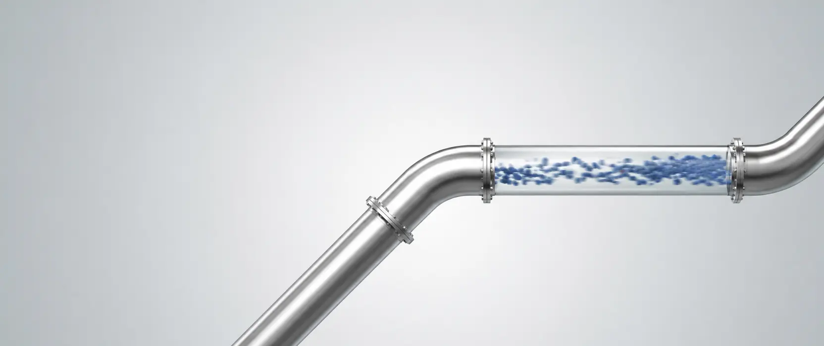
In an extraction system, the airflow transports particles from the source to the filter unit. For this to work, the flow velocity throughout the entire piping system must exceed a material-specific minimum value—the so-called suspension velocity of the material being extracted.
If the flow velocity falls below this value, particles drop out of the airflow and settle in the piping. Initially, deposits form that narrow the clear cross-section—which further reduces the velocity and accelerates the buildup of deposits. The result is a blockage that is often detected too late during operation.
On the other hand, an excessively high flow velocity increases wear—especially with abrasive materials such as metal chips or blasting media residues. Fast-moving hard particles erode pipe walls, bends, and separation units. The optimal flow velocity thus lies within a material-specific range—typically between 15 and 25 m/s for most industrial dusts, with variations depending on particle size, density, and shape.
How different materials behave in the airflow
Not all particles react the same way to the airflow. Light, fine dusts—such as wood dust or flour dust—are transported at nearly the speed of the air. Their suspension velocity is low, and the airflow carries them along without difficulty.
Heavy particles—metal chips, blasting media, granules—react more sluggishly. They follow the airflow with a delay, tend to settle in horizontal pipe sections, and require higher transport speeds to be safely guided through the piping system. Wet deposits or sticky materials present yet other challenges: Here, not only the velocity but also the pipe surface finish and the duct layout are relevant.
In practice, it has been shown that the biggest source of error in the design of extraction systems is the assumption that a uniform flow velocity is sufficient for all materials. Every material to be extracted has its own requirements—and a system that is correctly sized for light dusts can systematically fail when dealing with heavy particles.
What pipe diameter and system topology have to do with velocity
The flow velocity in an extraction system is not a property of the extractor alone—it is the result of the interaction between air flow rate and pipe cross-section. What matters is not the suction unit’s rated capacity, but the coordination of air flow rate, pipe dimensions, and system layout. With a constant air flow rate, the velocity increases as the cross-section decreases—and decreases as it increases.
This means: Anyone who retroactively changes pipe diameters, extends runs, or adds additional extraction points alters the flow velocity throughout the entire system—often unintentionally and with consequences for material that was previously transported safely. An extraction system must therefore be designed as a complete system, not as a combination of individual components.
What the EN 60335-2-69 standard requires—and what it does not regulate
The EN 60335-2-69 standard defines requirements for industrial vacuums and extraction systems—including filter classes for different types of dust, safety requirements for use in potentially explosive atmospheres, and labeling requirements. However, it does not specify universally applicable minimum transport velocities, as these depend on the material and cannot be standardized uniformly.
The design of the flow velocity is therefore the responsibility of the system designer—based on material-specific requirements, system topology, and operating conditions. The standard provides the framework. The design itself is an engineering task.
What a properly designed system demonstrates
In practice, it is evident that flow velocity is the most visible symptom of an incorrectly designed system—but rarely the actual cause. Blockages result from incorrect sizing. Wear occurs due to improper material selection or excessive velocity. Fine dust breakthrough occurs due to insufficient filtration.
A correctly designed extraction system maintains the flow velocity throughout the entire system within the material-specific optimal range—through coordinated pipe diameters, duct routing, and fan performance. This is not a matter of individual components, but of system architecture.
Classification
In such applications, it becomes clear that the design of an extraction system does not begin with the selection of the extractor, but with the analysis of the material to be extracted and the process conditions. RUWAC supports this design process—from determining the flow velocity and selecting the filter class to integrating the system into existing production environments.